Who says you can't have it all? Well, in this case, it's the collective thinking of Cervelo and Shimano. Cervelo loves the Magura hydraulic brake. Shimano, not so much. Shimano makes a Di2 electronic shifter with a brake lever for time trial bikes, but he issue is that Shimano doesn't make them for anyone else and they only make them in "cable pull" - NOT hydraulic.
So, Cervelo was faced with a choice. Di2 cable pulls from Shimano to round out the electronic cockpit, or Magura hydraulic brakes that offer great braking. Everyone thinks time trail bikes brake terribly and you should be in the aero bars anyway, so Cervelo went with the Magura and we now have no electronic shifting on the base bars - just the aero bars.
This makes sense for time trials, I suppose, but it is a drag for an all around bike where you need to commute through traffic and just get around between periods where you can safely ride in the aero bars.
I, like many before me, reject this proposition. I found it unacceptable. As a gentleman and a scholar, it was my duty to reject this compromise! I wanted it all. Thus began the mission to "hack" Di2 9070 and its eTube technology.
Prior versions of Di2 were more analog. A gentleman so inclined could splice a button into the wiring and presto, you could have it all. The gang at Shimano raised the stakes with 9070 version and the new eTube system. Those are wires you can't just snip. Plus, each button pod has a programable chip in it that works with the system to telling which derailleur to do what.
So, I put out the call for help, did a little research on my own and quickly developed a plan of action. Endurance Nation teammate, John Withrow, another gentleman that chooses to have it all from a shifting perspective, turned me on to a thread with detailed directions (thanks "veryoriginal") and I was ready to go.
The thread in question used the Di2 brake levers for the hack (Shimano ST-9071). This is $499 part. Yikes! Having it all was gonna hurt and that's an expense pair of parts to sacrifice if something went wrong. Then, I realized a more suitable donor part was the aero bar shifter pods (Shimano R-671). They were only $299. Sure my bike already had a set on the end of the aero bars, but I just needed the right chips to tell the derailleurs what to do.
Here is what you need:
- Shimano Di2 system on the bike (this is where the Cervelo P5 Starts)
- Shimano 5 port junction box (standard on P5)
- Shimano R-671 aero pods
- Small screw driver
- #2 and #3 Allen keys
- Small bladed knife or box cutter
- Wire snips and stripper
- Silicone Sealant
- Black electrical tape
To begin, start with the tear down.....

Shimano R-671 fresh from an on-line retailer

What you get in the box - Just two baggies....
Next, use a #3 allen key to remove the single bolt holding the assembly together. Discard the piece without the wire coming out. That is the theme of this tear down.

The allen comes out really easy. That is how you would install it on the end of the aero extension.
The next step is to remove the upper most two of the three little phillips screws. You could remove all three if you wanted, but they are a bit of pain and if you remove the top two, the bit with the wire will come away.

The little board assembly will just pop right out and you can pull off the little springs and toss them in the junk pile. See where i left the third screw...
The next step is to pop off the little white piece of plastic. It has no value and basically just protects the chip. It is glued to the chip frame and a little blade can make it come off cleanly.

Just put the blade in and wiggle it a bit to break up the glue.
Pro tip: See the red tape in the picture? I out that there to keep the pieces straight. in this case "right is red". Meaning, the chip is already factory programmed for the right side and will run the rear derailleur. It is programmable, but if you keep them straight to begin with, you will not need to re-program them.
Once the white plastic is gone, the tear down is almost done.
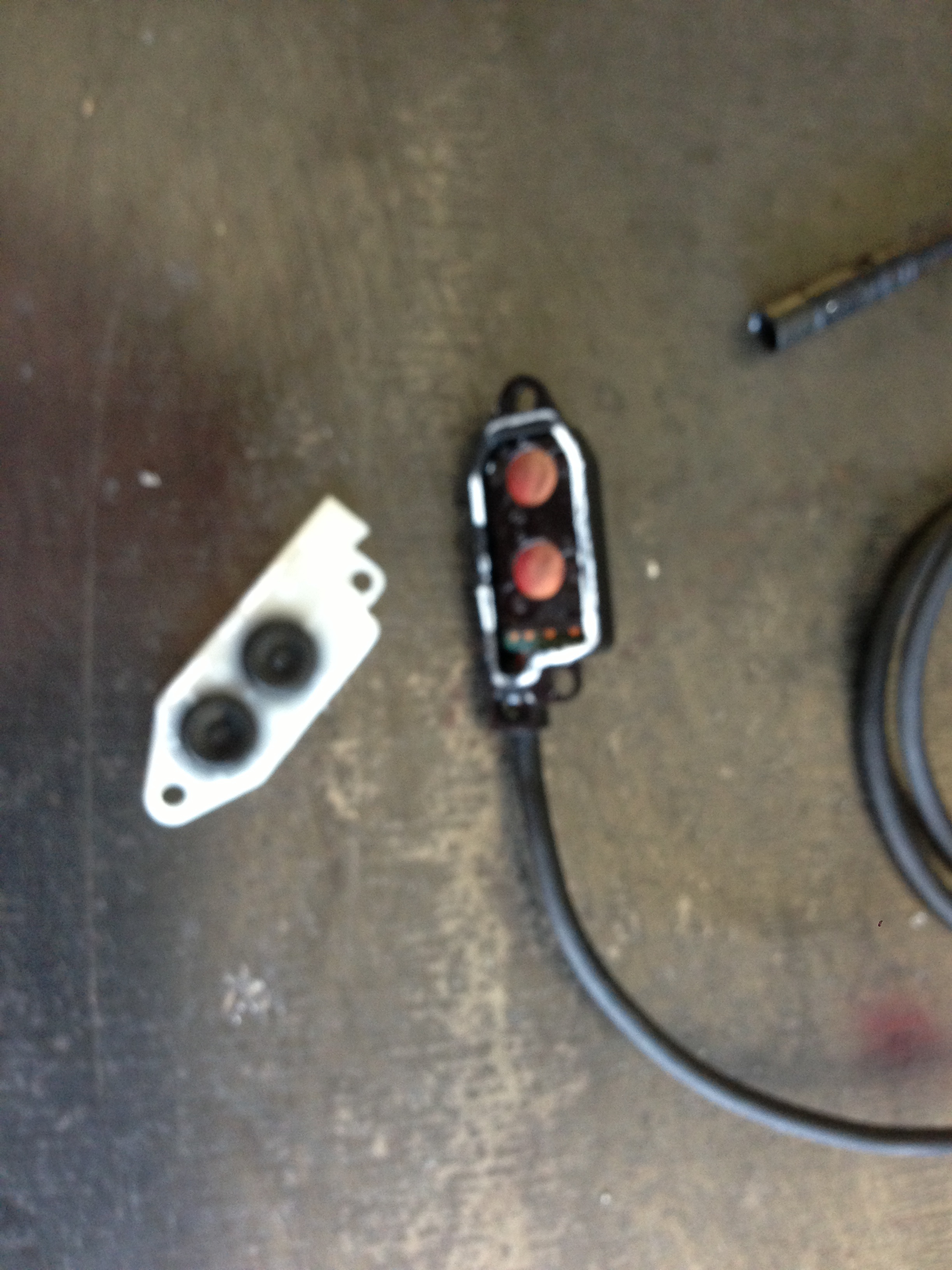
The last piece between us and the board is the little black plastic bit that holds the silver-ish dots in place.
The black plastic piece is held on by four little plastic posts. If you use a blade in the gaps around the part, you carefully pry it loose. Be careful not to hurt the board!

The target for the soldering is the pair of gold dots with their associated horseshoes (technical term)
It's now time to meet your new buttons.... Super cheap, but really effective little jobs from CatEye. $9.00 per pair!
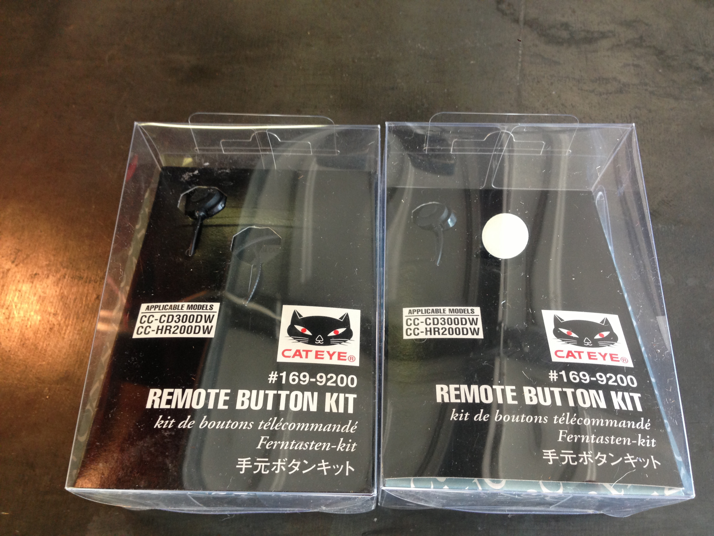
You need two sets. One set for each side/derailleur.
Open the box and you find a lot of random stuff. Toss it all. You only need the two buttons.


Measure 5-6" and then cut the wire off. Each button has two small copper wire. Splice off the black sleeve and then strip and separate the inner pair.
Now you get to start soldering! In my case, this was the job of the steady hands of Harry Morris, fellow PTC member and electronics genius!
It DOES NOT matter which color wire you solder to which spot. The key is to ensure the solder does not creep across the gap between terminals and wreck the circuit. You also want to ensure the stripped wires don't touch for the same reason. In this case, we used a little electrical tape as an insulator.
To get a good connection, Harry "tinned" or pre-applied a little solder to the wires and the board before making the connection. In the picture below. You can see the other pair on the board already tinned.

Like the game "Operation", it takes a steady hand....
One button down. To get the other done, just repeat....

Presto! You now have buttons...
One down, one to go. The steps for the left side are identical.
Pro Tip: To really protect the soldering and weather proof the hack, fill the exposed area of the hack with silicone sealant. I just used a brand a from the hardware store and any will work. It can get messy, so invest a little time in doing it cleanly.

After the sealant cures, wrap nicely in black electrical tape for more protection. The hack is complete!
To test your work, just crack open the cockpit to access the 5-port junction box standard on the P5. There are two open ports on the box. Just plug the hack in. No need to fish the wires through the base bar to test your work.

Open port on the box.
Right side (remember the red tape) is plugged in and shifting LIKE A DREAM!
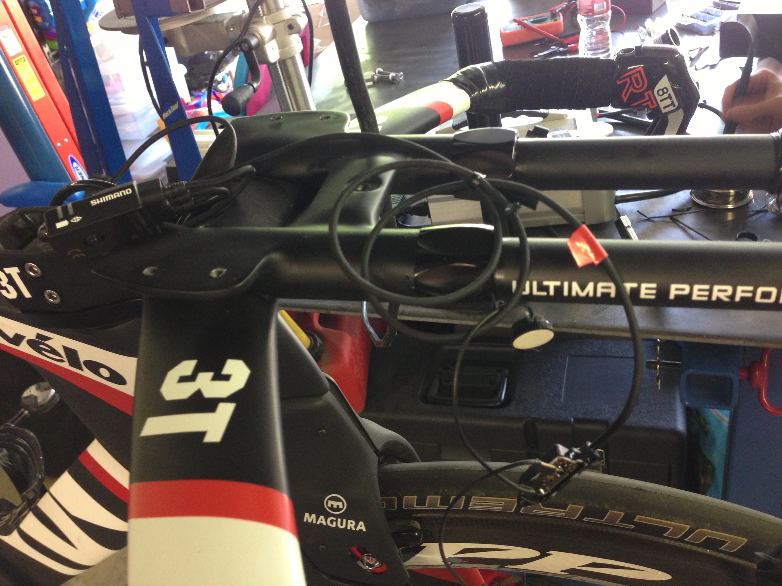
The final step is a fishing trip. Run the now tested hack back through the base bars, pull the buttons though the holes in the bottom of the base bars, stick the buttons where you want and re-tape!

The finished product is super clean and works like a charm!
Pro Tip: Another sweet move is how to orient the buttons. I set mine up so the top button moves up to the big ring and the lower button moves down to the small ring. On the other side, I used the same logic for moving up and down the cassette.
This hack was super simple! The only tricky part is the steady hands needed for the soldering. The tear down and prep is totally a one banana job on a 1-10 banana scale. So easy a cave man could do it. To make the solder connection work, make sure you have a soldering iron with the smallest tip you can find. These connection are not microscopic, but they are small and you need some precision. The rest is just running the cables. The best part of this hack is that you have left your system totally intact. If the hack goes bad, just unplug it from the junction box and you are back to where you started. The only risk is cash tied up in the R-671 aero shifters. You have not hacked the 9070 system at all.
In my opinion, this hack is the best DIY modification for P5 you could do. Hands down, the best. It just makes the bike so much more fun to ride and basically creates a ton of extra value. Shifting from two spots is why TT bikes should have Di2 in the first place.
I love it!
The other cool thought is that if you have a 9070 system, all you need is a 5 junction box and this hack to put custom buttons anywhere you want....
Thanks for reading!